


 As the process industry continues to achieve more efficient and productive plant design, plant engineers and technicians are faced, almost daily, with new equipment designs and applications. One product, a valve actuator, may be described by some as simply a black box, having an input (power supply or signal), an output (torque), and a mechanism or circuitry to operate a valve. Those who select control valves will quickly see that a variety of valve actuators are available to meet most individual or plant wide valve automation requirements. In order to make the best technical and economical choice, an engineer must know the factors that are most important for the selection of actuators for plant wide valve automation. Where the quality of a valve depends on the mechanical design, the metallurgy, and the machining, its performance in the control loop is often dictated by the actuator.
The decision to automate a valve is usually based on one or all of the following considerations.
- Safety
- Reliable operation
- Control and process system performance
- Inaccessible or remote valve location
- Cost
- Excessive valve torque
- Emergency response and whether it is fail-safe
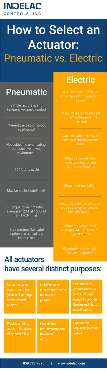
All actuators have several distinct purposes.
1. Move the valve closure member (disc, ball, or plug) to the desired position. Not only must the actuator provide enough torque or thrust to move the closure member under the most severe conditions, it must also be fitted with the appropriate controls to direct it.
2. Hold the valve closure member in the desired position. Particularly in throttling applications where fluids may create a dynamic torque, actuators should have adequate spring or fluid power or mechanical stiffness to overcome this phenomenon.
3. Seat the valve closure member with sufficient torque to provide the desired shutoff specification. A butterfly valve for instance is fully seated (closed) when the disc is positioned in a resilient liner (seat). In this rotary position the valve stem torque is at its highest. Actuator sizing for torque-seated butterfly valves may require special accessories particularly on electric actuators to ensure that sufficient torque is sustained in the closed position.
4. Provide a failure mode in the event of system failure. This may be fully opened, closed, or as-is depending upon the application. Certain failure mode requirements may eliminate electric actuators yet be ideal for pneumatic or electrohydraulic units.
5. Provide the required rotational travel (90°, 180°, etc.). Valves requiring more than 90° of rotation include multiported valves. A few pneumatic actuator manufacturers offer 180° actuators. For greater than 180°, electric actuators are usually preferred because they are electrically, not mechanically, limited in rotation.
6. Provide the required operating speed. All actuators may be regulated in cycle speed depending on the control circuit elements used.
Fast cycle speeds (less than one-half the standard actuator cycle time) require careful valve selection. The physical shocks associated with fast cycling can damage the valve parts—especially when combined with high cycle rates. Special preparation of pneumatic actuators—including special solenoids, piping, and quick-exhaust valves—may be required to achieve high cycle speeds.
The cycle speeds of electric actuators cannot be increased, only slowed. This is easily accomplished with the specification of either special cycle times or with the addition of an electronic speed control card. Special cycle times are achieved with a different gearing mechanism which also affects output torque. The electronic speed control is infinitely adjustable and can reduce the effective actuator speed up to 20 times without the need for special gearing. Output torque of the actuator is not affected where speed cards are used. Pneumatic actuators can be slowed by the use of speed control valves in the air piping. One speed control valve will slow speed in one direction, while two are required to slow speed in both directions. Speed controls do not affect the output torque of pneumatic actuators.
High cycle rates will require special selection and preparation of valves and actuators. A high cycle rate for pneumatic actuators is de-fined as cycling continuously in excess of 30 times per hour; electric actuators used in excess of a 25 percent duty cycle are said to have a high cycle rate. High cycle rates place additional stress and wear on the valve stem. The small amount of play between the actuator, stem, and ball increases the wear in the stem in high cycle rate applications. This is minimized with special preparation to assure long life of the valve package.
Pneumatic and electric actuators compared
At times it is necessary for a process engineer to choose between a pneumatically or an electrically actuated valve for a process system. There are advantages to both styles, and it is valuable to have data available to make the best choice.
Compatibility (Power Source)
First and foremost in the selection of an actuator type (pneumatic or electric) is to determine the most effective power source for the actuator. Points to consider are:![]()
- Power source availability
- Torque at the valve stem
- Failure mode
- Control accessories
- Speed of operation
- Frequency of operation
- Plant environment
- Size of valve
- System component costs
- System maintenance
The most practical pneumatic actuators utilize an air pressure supply of 40 to 120 psi (3 to 8 bar). Generally they are sized for a supply pressure of 60 to 80 psi (4 to 6 bar). Higher air pressure is usually difficult to guarantee and lower pressures require a very large diameter piston or diaphragm to generate desirable operating torque.
Electric actuators are often used with a 115 VAC power supply but are available with a wide variety of AC and DC motors in single phase and three phase.
Temperature range
Both pneumatic and electric actuators may be used in a wide temperature range. The standard temperature range of a pneumatic actuator is from -4 to 174°F (-20 to 80°C) but may be extended to -40 to 250°F (-40 to 121°C) with optional seals, bearings and grease. If control accessories are used (limit switches, solenoid valves etc.) they may not have the same temperature rating as the actuator and this should be considered in all applications.
In low temperature applications the quality of the supply air in relation to dew point should be considered. Dew point is the temperature at which condensation occurs in air. Condensate may freeze and block air supply lines making the actuator inoperable.
Electric actuators are available in a temperature range of -40 to 150°F (-40 to 65°C). When used outdoors an electric actuator should be sealed from the environment to prevent the introduction of moisture to the internal workings. Condensation may still form inside, if drawn from the power supply conduit, which may have captured rainwater prior to installation. Also, since motors warm the inside of the actuator enclosure when it is operating and cools it when it is not, temperature fluctuations may cause environmental "breathing" and condensation. For this reason all electric actuators used outdoors should be fitted with a heater.
Hazardous Areas
It is sometimes difficult to justify the use of electric actuators in a hazardous environment, but if compressed air is not available or if a pneumatic actuator will not provide the operating characteristics required, then an electric actuator with a properly classified enclosure may be used.

NEMA guidelines
The National Electrical Manufacturers Association (NEMA) has set up guidelines for the construction and installation of electric actuators (and other electrical devices) for use in hazardous areas. The NEMA 7 guideline reads:
VII Hazardous Location Class I (Explosive Gas or Vapor) Meets application requirements of National Electrical Code; conforms with specifications of Underwriters' Laboratories, Inc., used for atmosphere containing gasoline, hexane, naphtha, benzene, butane, propane, acetone, benzol, lacquer-solvent vapors, and natural gas.
Almost all electric actuator manufacturers have an option for a version of their standard product line that conforms to NEMA 7.
On the other hand, pneumatic actuators are inherently “explosion-proof”. When electric controls are used with pneumatic actuators in hazardous areas they are generally more cost effective than electric actuators. Solenoid-operated pilot valves may be mounted and powered in a nonhazardous area and piped to the actuator. Limit switches -for position indication- may be housed in a NEMA 7 enclosure. The inherent safety of pneumatic actuators in hazardous areas makes them a practical choice in these applications.

Spring return
Another safety accessory widely specified in the process industries on valve actuators is the spring-return (fail-safe) option. Upon power or signal failure a spring-return actuator drives the valve to a pre-determined safe position. This is a practical and inexpensive option with pneumatic actuators and is an important reason for the wide use of pneumatic actuators throughout the industry.
Where springs are not practical because of actuator size or weight, or if a double-acting unit is already installed, an accumulator tank may be installed to store air pressure.
Electric actuators are not widely available in a spring return version; however, a battery backup system is an elegant solution.
To accomplish the spring-return function an electro-hydraulic actuator is often a good choice. Electro-hydraulic actuation is achieved by energizing a hydraulic pump, which pressurizes a spring-return cylinder. Upon power failure the spring action drives the actuator to the original position. Because only an electric power supply is required for this self-contained unit it is a practical approach to fail-safe electric valve actuation.

Performance characteristics
Before specifying a pneumatic or electric actuator for valve automation it is important to consider a few of the key performance characteristics of each.
Duty cycle
Pneumatic actuators have a 100 percent duty cycle. In fact, the harder they work, the better they work.
Electric actuators are most commonly available with 25 percent duty cycle motors. This means that to prevent overheating in high cycle applications the motor must rest frequently. Because most on-off automated valves remain idle 95 percent of the time duty cycle is not usually an issue. With optional motors and/or capacitors an electric actuator may be upgraded to 100 percent duty cycle.

Stalling
Pneumatic actuators may be stalled indefinitely without overheating.
Electric actuators should not be stalled. Stalling an electric actuator draws excessive current, which generates heat in the motor and can cause damage. Torque switches or heat and current sensors are often installed in electric actuators to protect the device.
Speed control
The ability to control the speed of a pneumatic actuator is an important advantage of the design. The simplest way to control the speed is to fit the actuator with a variable orifice (needle valve) at the exhaust port of the air pilot.
 Modulating control
Since electric actuators are geared motors it is impossible to make them cycle faster unless a gearing change is made. For slower operation a pulsing circuit may be added as an option.
In modulating service an electric actuator interfaces well with existing electronic control systems and eliminates the need for electro-pneumatic controls. A pneumatic or electro-pneumatic positioner is used with pneumatic actuators to provide a means of controlling the valve position.
Torque-to-weight ratio
Electric actuators have a high torque-to-weight ratio above 4,000 lbf.in. (450 Nm). Pneumatic actuators have an excellent torque-to-weight ratio below 4,000 lbf.in.
Summary of pneumatic and electric actuators
This table of characteristics summarizes the comparison of pneumatic and electric actuators.
Found this article interesting? Read 2nd and/or 3rd part about how to develop a complete specification for each of the elements in the automation process.

