


TOOLS REQUIRED
3/16” wide flat head screw driver.
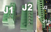
NOTE
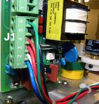
J1 has 6 terminal connections and J2 is on top.
PLEASE READ THESE INSTRUCTIONS COMPLETELY BEFORE BEGINNING
-
Turn off power to actuator.

-
Loosen and remove cover screws.
-
Remove cover.
-
Remove switches.

Remove terminal strip and bracket.
-
(Only on the L-series) Butt connect an additional length of white wire to the yellow motor wire.
-
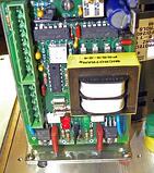
Remove the PCB from its packaging.
-
Remove terminal strips J1 and J2 from the PCB.
-
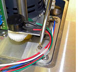
Mount the bracket with 6-32 screws to the actuator’s base plate.
-
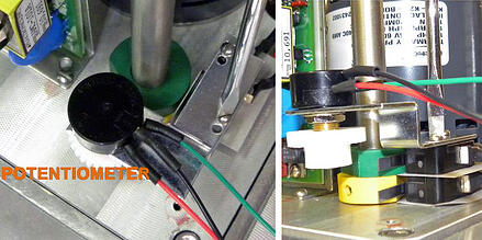
Mount potentiometer with the existing switches that you removed in step 4 to the actuator base plate using 4-40 screws (M-series will use spacers between switches).
-
Take the black, normally open, switch wires and using a push on connecter connect them to the capacitor. NO closed switch, located on the bottom, goes with the red motor wire. NO open switch, located on the top, goes with the blue motor wire.
-
Secure all other wires with a tie down.
-
Connect the common blue wire from the open switch to terminal position # 1 on J1.
-
Connect the white motor wire to terminal position #2 on J1.
-
Connect the common red wire from the closed switch to terminal position #3 on J1.
-
Connect the red potentiometer to terminal position #4 on J1.
-
Connect the black potentiometer to the terminal position #5 on J1.
-
Connect the green potentiometer to the terminal position # 6 on J1.
-
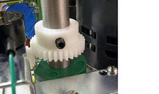
Place the potentiometer gear down over the shaft with the gear down and the set screw up.
-
Using the manual over ride position the output shaft in the mid position (45 degrees).
-
Loosen the set screw in pot gear installed on the output shaft.
-
Unplug J1 from the PCB.Using a multi-meter measure the resistance between J1-5 and J1-6. The pot is a 1K pot so with the actuator in the mid position the optimal resistance between J1-5 and J1-6 is 500 ohms which is the center position of the pot.
-
Rotate the pot gear until the pot resistance is as close to 500 ohms as possible. Be sure the pot gears fit snugly together then tighten the set screw. DO NOT OVER TIGHTEN you may strip the threads.
-
Wire the actuator in accordance with the wiring diagram.
-
Turn on the power supply.
-
Send a 4mA signal to the actuator.
-
Visually check the position of the valve.
-
To increase travel rotate zero (z) trim potentiometer clockwise (CW).
-
To decrease travel rotate (z) trim potentiometer counter clockwise (CCW).
-
Send a 20mA signal to the actuator.
-
Visually check the valve position.
-
To increase travel rotate the span (s) trim potentiometer CW.
-
To decrease travel rotate (s) trim potentiometer CCW.

*SINCE THE ZERO AND SPAN TRIM POTS ARE NON-INTERACTING NO FURTHER CALIBRATION IS NECESSARY.
