The simple short phrase “fail-safe actuator” conjures a vision of a wide range of different actuators. In fact, when you Google “fail-safe actuator,” you get 1,910,000 results. It’s clear that those who need a fail-safe actuator for an application have their work cut out for them selecting the right actuator. Perhaps the best place to start would be to address: what is a fail-safe actuator?
By its most basic definition, a fail-safe actuator is a machine that stores energy to position a driven device to a predetermined safe position should power be lost. TermWiki describes a spring return actuator (another term for fail-safe actuator) as: “A valve actuator that compresses an internal spring when the actuator moves the flow control element away from its starting position (open or closed) and then uses the energy stored in the spring to move the flow control element back toward its starting position.”

With this definition in mind, we can look next at how many different types of fail-safe actuators are available. There are three basic categories of pneumatic, electric and electrohydraulic. However, within each category, a wide range of different designs are available. For example, within the pneumatic family, there is rack and pinion, cylinder, scotch yoke, vane, diaphragm and more—each is designed for a specific group of applications. A few examples of different electric fail-safe actuator designs are the battery backup system, rack and pinion and rotary electric.
The next step after understanding what a fail-safe (spring return) actuator is and understanding how many categories there are would be to provide an overview of all the different types available. Since that’s not practical in one article, here are a few of the more commonly used:
RACK AND PINION SPRING RETURN
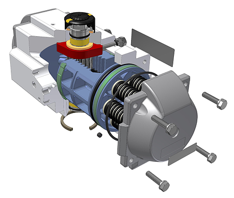
The rack and pinion spring return actuator is a relatively simple design compressed air drives a piston inside a cylinder, the piston drives a toothed rack. The teeth of the rack interlock with those of a pinion, which is turned as the piston drives the rack. As the pinion rotates, it provides the system with rotating force. As the piston/rack drives the pinion, it also compresses a series of springs; upon loss of compressed air, the springs return the piston to its starting position (Figure 1).
Figure 1. Rack & pinion pneumatic fail-safe
The pneumatic spring return actuator is one of the most widely used failsafe actuators in the world. This is primarily because of the simplicity of operation of the pneumatic actuator and the low initial investment required, particularly when air lines are already available. In addition to low initial cost, there are other reasons to consider pneumatic actuators for fail-safe applications. Such actuators are light weight, fast acting, no affected by duty cycle, readily available and easy to install. In addition there are a wide range of torques to select from and vendors to assist with selection.
Meanwhile, there are also some operational issues to consider. These include requirements for airline installation, maintenance and low ambient temperature; the reality that moisture in air lines can pose a problem; the types of control needed; cost of electricity for the compressor; and the fact pneumatic actuators are not as easily adapted to some of the more sophisticated control systems in use today. According to the Department of Energy, 24% of the annual cost of compressed air is from maintenance, equipment and installation while 76% is from direct costs of electricity for the compressor.
ROTARY FAIL-SAFE ELECTRIC ACTUATOR
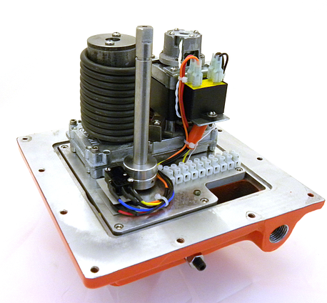
The fail-safe electric actuator (Figure 2) uses an electric motor to drive a series of gears to rotate a drive shaft counter clockwise or clockwise depending on the desired fail-safe position. As the drive shaft rotates, a series of springs are compressed, or in some styles a spiral spring is tensioned, storing energy in the springs. As the output shaft rotates, it provides the system with rotating force. The start and ending positions are generally controlled by limit switches. At the end of the power stroke, the drive shaft is held in position by an electromechanical brake or in some spring return designs, a clutch system. Upon loss of electrical power, the springs return the drive shaft to its starting position.

Figure 2. Output rotary fail-safe electric actuator
The electric spring return actuator has been gaining in popularity over the past decade. This is because of moderate initial unit cost, low installation, operation and maintenance costs, and accurate control. Also, increasing torque range and advances in product design have opened up a wider range of applications. When pressurized air is not available or the cost of installing air lines is too expensive, the fail-safe electric actuator is a viable alternative to pneumatic spring return actuators.
ELECTRO-HYDRAULIC
Hydraulic systems are generally self-contained closed-circuit systems. The hydraulic fluid used for control is filtered and stored in a reservoir. The liquid in the hydraulic system must be recirculated, thus requiring more maintenance and also storage because liquids do not compress. This is beneficial to control—because the liquid cannot be compressed, rigidity is provided when the liquid is not flowing and precision is provided when flow occurs.
Electro-hydraulic fail-safe actuators are available with high torque, they are fast acting, and they provide control with precision. On the other hand, these fail-safe actuators are costly and prone to oil leaks requiring some maintenance and can be affected by low-ambient temperatures if precautions are not taken.
From what we’ve been able to cove in this short column, it’s easy to see that when selecting a fail-safe actuator, the most important thing is to know your application requirements and the available budget. Some considerations for selection are: the power source available; whether new lines have to be installed in the case of air; and whether the air compressor is large enough for the installation needs. Other considerations are the type of valve being controlled, the torque required (we recommend a sufficient safety factor of at least 25%), the type of control, whether you have on/off or modulating, the ambient temperature and the long-term operating cost.


